Massey Ferguson 565 linkage renovation

Massey Ferguson 565 linkage made somewhat up and down movement by itself. With heavier load something knocked inside transmission housing like asking to get out. Still pumped well when position lever was on constant pumping. I decided to watch if there were worn out parts or if I could adjust or do something else. I didn't have workshop manual when starting this, but all parts found a place eventually. In this picture there is empty sowing machine in link arms. When seeded 565 had front weights, double wheels and auxiliary lift cylinder in between tow hitch and seeder's top link bracket.

I've taken off cover panels, wiring, fuel filling pipe, cross support bar and cabin's upper floor in which the driver's seat is fastened.

There is about 15 cm room between cabin and lift cover. The curved fuel filling tube is also here in the middle, 575 and 590 it would be on the left, coming straight up from fuel tank and giving more room in the middle.
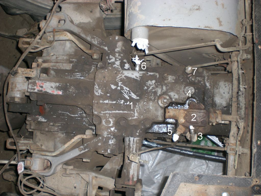
The lift cover of Massey Ferguson with only linkage pump hydraulics A.K.A married to the 3-way selector valve. If this tractor had other pump for external hydraulics, then it's pressure and return pipes would come up between fuel tank and tractor body, see auxiliary pump page.
1. The lift cover bolted on the transmission housing.
2. 3-way selector valve with 3 positions, EXT1, EXT2 and middle position, in which the linkage acts normally. To operate this valve, there is a lever in the cabin with EXT1 and EXT2 text or then there is not. EXT-positions lead linkage pump output to external use.
3. Selector valve's EXT2 output. The link arms stay in the position they were when switched on, they tend to sink as time goes. To get pressure the position lever on quadrant must be on constant pumping. It can also be in pressure control sector if lower pressure is needed. Maximum pressure is about 210 bar.
4. EXT1 connection is actually in both plugs. This acts like EXT2, but link arms rise first up to highest position, could be used with rear weight for example. The linkage works as a linkage only in the middle position of valve.
5. Free return alias tankline leads into transmission housing oil reservoir.
6. This hole is for installation of linkage control mechanism, but can used as tankline. Oil don't stream below oil level on either of these.
7. In older models without selector valve this was often used for trailer tipping. Link arms rise before tipping cylinder, cause there's connection to internal lift cylinder and this can be used for lift assistor ram alias external lift cylinder. Below this output and selector is a bore across lift cover with Allen plugs on both sides of the cover.

The selector valve removed; brings in sight the pressure pipe from linkage pump. In this model the pipe could now be removed and the O-rings changed. These O-rings leaking are often reason for missing force.
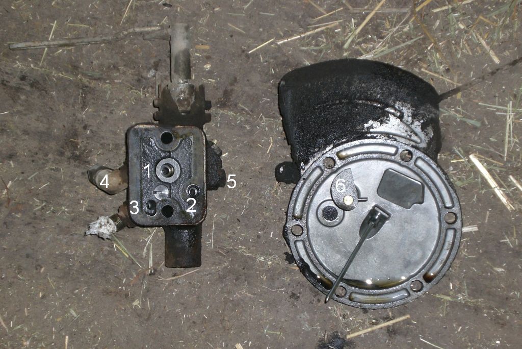
The selector valve and right side round cover.
1. Cavity for pressure pipe from linkage pump, below it may be a relief valve or alternatively have something to do with 5, I'm not sure.
2. Connection to lift cylinder (ram) bore.
3. Free return (tankline).
4. EXT2
5. EXT1, twin outlet.
6. Response control for linkage's reaction speed for example in ploughing. Controls linkage's lowering speed as well. The eccentric disc moves a lever on pump's side. In practise linkage gets down almost independently of weight in lower link arms, but oil viscosity has an affect. In Finland I've moved this in autumn after first frosty days to get the tow hitch down more rapidly. In spring have turned the other direction to get heavy sowing machine down safely.
The cover has also a dipstick for common transmission and hydraulics oil.

I took off lift cover's jointing bolts and placed a steel bar between the rear axle housing and the cross shaft. Twisted the cover open to get my fingers a grab on front edge of cover. Managed to pull the cover up and then looked for a support to lay the cover on and my possibilities to reach any. The pin jointing upper link arms and lift rods acted as a hinge, the pin in the upper end of top link fork could do the same thing.

The lift ram in the front. Maybe the only weaker point in linkage is that lift cover can snap in two pieces. The pressure inside cylinder makes a hard twisting load the cover can't stand, if the bolts are not tight enough. Alternatively there is a pressure shock when driven to a hump on the road and machine jumps up and then comes down, the ram don't reject upside movement in Fergie. The cover breaks, which is not noticed until the bolts get loose or the central housing snaps too. Heavy weight in linkage doesn't stress much, if assistor ram is used to smooth the pressure. The castings can also change their form by time causing extra stress to parts. Of course malfunction on pressure control can lead to breaking too, cause the piston pump is capable to produce very high pressure.
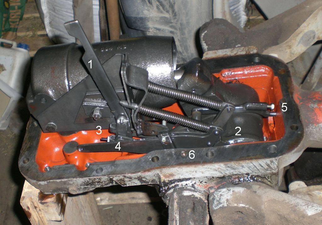
The lift cover's mechanism to control the Ferguson System linkage.
1. The spool valve for linkage control integrated in pump is directed by this rod.
2. The cam on link arm cross shaft tells position of the arms to mechanism.
3. Moves part 1 depending on the status of 2 and the position control lever. This is the lever next to driver's seat and now it's on quadrant's rear sector (down-position-up-transport-constant pumping). Part 3 moves back and forth on rolls, also lever moves this by pressing it with a roll.
4. When the position lever is on quadrant's front alias pressure control sector, this rod directs pump's pressure control system. Inside lift cylinder it remains chosen pressure, can be for example utilized to move more weight to rear wheels..
5. Draft control's sensor and it's limiter bolt. The pin probes if the top link is pulling or pushing, when ploughed for example. Also this moves part 1 using rolls, when outer alias draft control lever is on quadrant, unless it's on most rear position.
6. Locking bolt for quadrant lever's shafts. In 565 levers aren't really on these shafts, but inside cabin and actuate with rods to solid and hollow shaft.
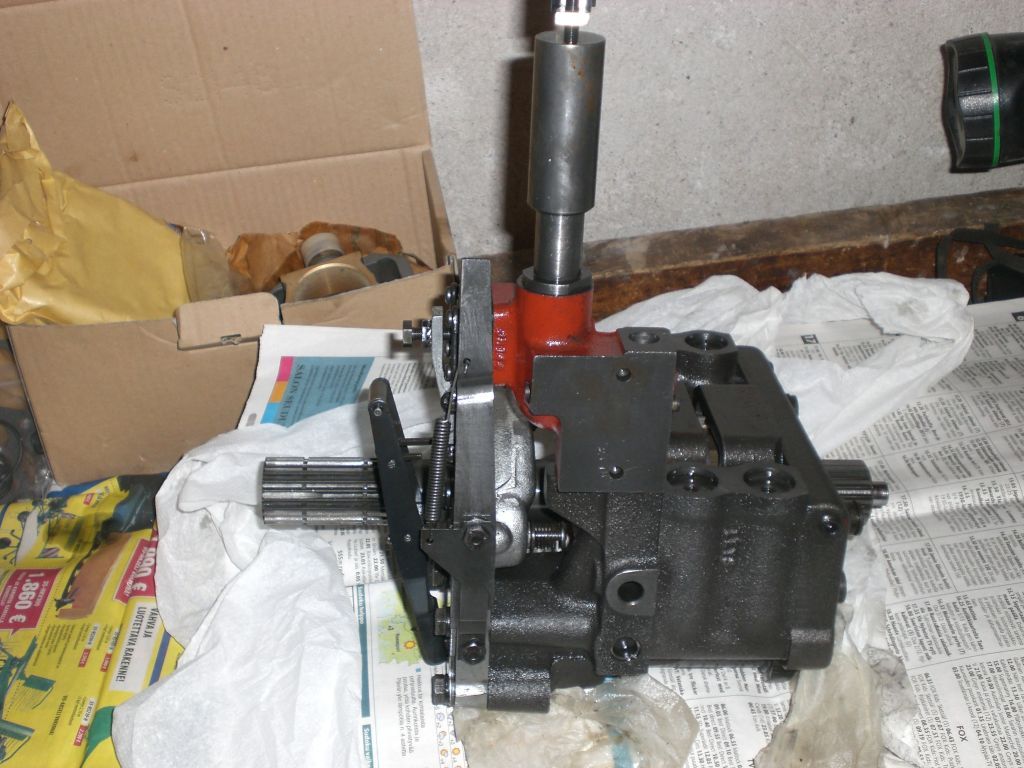
The linkage pump on the table. Own page for pump's renovation here. To remove the pump I had to split the tractor, more about it later. Pump's output is straight piped to lift ram, pumps all the time against pressure in cylinder. The linkage's steering valve is integrated in pump and can throttle pump's suction through inlet. When the valve is on the right, suction is open and the pump drives oil to cylinder and link arms get up. When the control mechanism moves the valve to the left, suction is closed and valve let's oil in outlet and ram to empty out to central housing; The linkage is lowered. The steering alias control valve's spool is spinned a quarter round and back to eliminate friction on back and forth movement.
The system is mystic in many levels; lots of imagination used to develop it. At first rejecting the suction destroys ordinary hydraulic pump. For example gear wheel type pump needs pumped oil for both lubrication and sealing. However this piston pump is sunken in oil and because of open structure the lubrication happens all the time, although the pump runs dry.
The function of the linkage control system in general is quite impossible to profile. It's like an analogical PI-controller done with mechanics and hydraulics. Electrical analog controllers were used before the computer age and are still used too. For example ordinary amplifier (at least for old timers) used to music playback is actually so called P-controller. It includes differential amplifier and negative feedback loop from output. The feedback directs the amplifier to keep output on constant level, though loudspeaker affects a heavy load, that makes output to stall. In PI-controller the negative feedback is delayed to gain more accurate output with a cost of worsened stability and the controller is vulnerable to saw back and forth, if parameters are wrong. In Ferguson linkage delay in feedback comes along naturally because of mechanic and hydraulic function. It has the same ripple in action and instability comes forth as knocking with heavy load when setting parameters are out of range. Wearing of parts has an affect to settings and bad settings increase wearing. In my linkage I didn't find broken parts. I haven't opened pump cylinder valves, maybe something in them.
The Ferguson System is developed in 1930's, analog controllers are probably older innovation. Will return to linkage settings when have read the workshop manual.
Besides the steering pump, which I replaced with a 300-series tandem pump, the linkage pump is the only hydraulic pump in this tractor. On top of the linkage pump the more equipped models have MultiPower pump or Auxiliary pump. The Auxiliary pump is tandem pump with separate gears for low MP pressure and auxiliary hydraulics high pressure. The principle is like in 300-series, though place is different. With auxiliary pump external hydraulics can be used without paralysing the linkage. To produce more flow linkage pump's feed can be taken along with selector valve using right hoses and non-return valves. MP pump is only for hydraulic stacks like MultiPower, independent PTO and 4WD drive stacks.
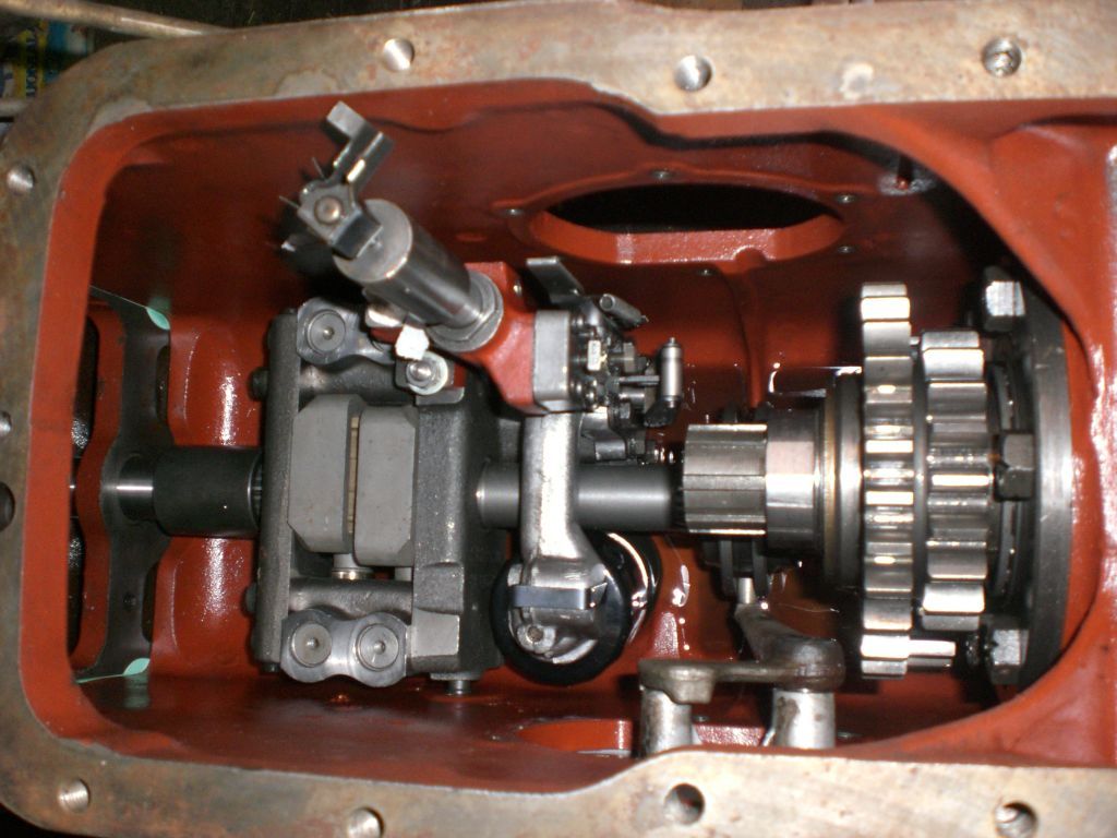
In this picture the renewed linkage pump is installed in central housing. Top of it should be drive transmission shaft, that was removed by pulling a socket off and sliding a splined sleeve aside. Because of PTO gears on the right the pump can't be removed without splitting the tractor. Before lowering the lift cover I put a string in the dipstick hole and beyond that pressure control cylinder to steering valve lever (a small roll on upper end) and same way back. Doing this I could pull the lever close to pump. The levers went right way around when lowering the lift cover and I could pull the string out via dipstick hole.

There is a hatch in 565 cabin floor to bring central and extension housing jointing in sight. I installed a Walvoil valve table with 3/8 inch ducts underside of cabin upper floor.

The cabin was hanged to roof supports before disconnecting the tractor body. Then removed the shield under fuel tank and opened the brake rods et cetera.
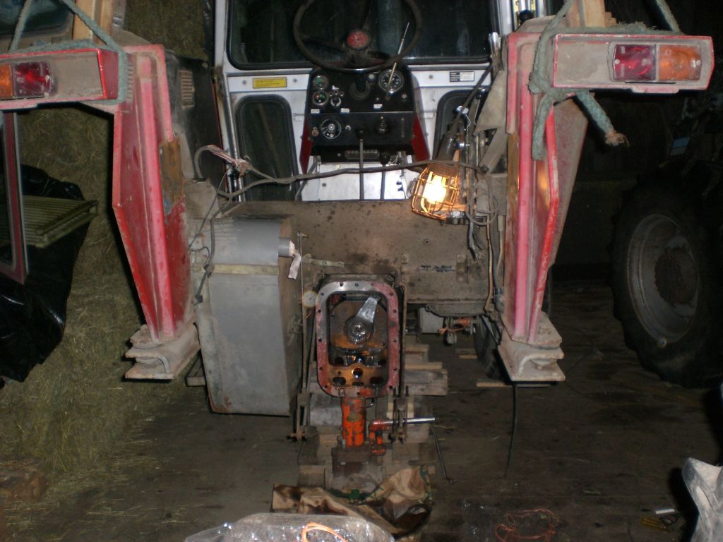
The gearbox was lifted with hydraulic jack and supported with log bedding. There are wooden shocks between front axle and it's housing to make the axle rigid and keep the front end from falling.
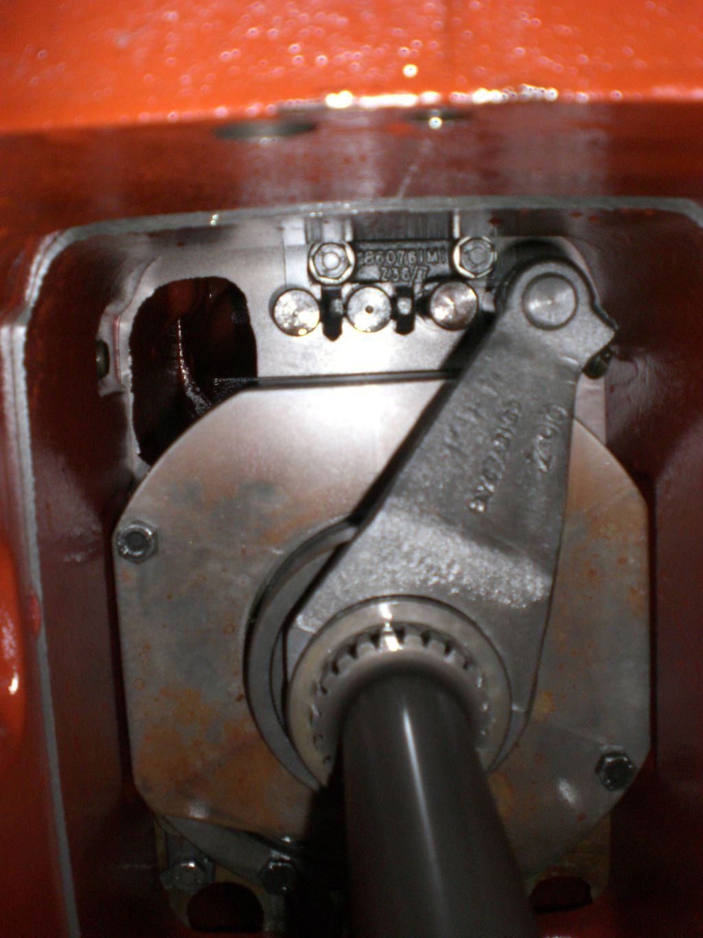
The multiplier for lowering speed 1:4 and gear rod's fork. Up there can be seen 3 heads of gear rods. These are for engaging basic 4 forward and 1 reverse gears. There is also a device, that prevents to move more than one rod simultaneously to ensure only one gear is switched.

I renewed that needle bearing in extension housing's PTO transmission line. The short shaft had wearing too, but made nothing to it. The linkage pump's shaft is part of PTO transmission and the pump is fastened with pins to side walls of central housing.

When the body casting was not in a way, it was easy to renew fuel gauge's sensor. The old pontoon was half full of fuel so it couldn't float. In this tractor fuel has always ran out when the gauge shows half tank and I've heard other this kind 565 down here. Something to do with 565 having a smaller tank than 575 or 590? Maybe the sensors are similar or something. For this after taking the photo I twisted the pontoon arm upwards and shorter to get wound resistor's full length in use. The result was OK.

The tail end is almost balanced on the rear tyres. Could be pushed around like a wheelbarrow, if there were handles in the back or lower links were fastened somehow.
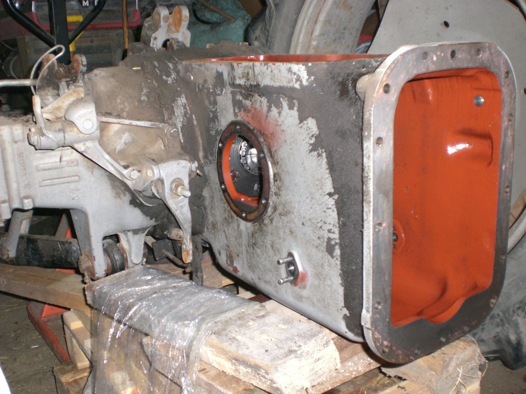
The holes for right side round cover and fastening pins of the linkage pump.

The left side of the central housing.

The left side round cover and PTO switch on lever. A 500-series MF with an auxiliary pump here are installed it's pressure and return pipes that come up between fuel tank and body. In here places for pipes too, but are not holed.

The lever's roll pin was loose and PTO switching didn't work properly. I bored the hole a bit and put in a larger socket. This tractor has Live PTO with double clutch and no ground speed PTO.

The gears to lower PTO speed 1000/540 rpm. The PTO speed can be chosen by using a different PTO shaft. 540 shaft is splined under rearward and 1000 under front gear wheel. The double gear wheel on top is mounted on to bearings on pinion shaft. The linkage pump rotates 1000 rpm (high flow pump, 26 l/min). In the MF with ground speed PTO opportunity it would rotate 540 rpm (standard pump, 16 l/min) on engine turns 1700 rpm. The practise is like this in 100-series.

I cleaned the bottom of the empty housing at this point. 540 rpm gear wheel has bearings in casting. That sliding shim is upside down in picture.

Some parts removed from transmission housing.
1. 540 rpm gear and bearing for 2 on it.
2. 1000 rpm gear.
3. Sleeves for PTO engaging and connection to pump shaft.
4. The double gear wheel on pinion shaft.
5. The short PTO shaft for extension housing and splined sleeves.
6. The drive transmission shaft multiplier-pinion and sleeve with holes for a socket.

Same parts, different angle. That 21-grooved spline is similar to one used commonly in 1000 rpm power take-off stumps. Parts were then put back.

When lowered the lift cover was fastened to the pin in top link fork. There was a rope link in bolt holes frontward cover to get a grip with my left hand. Another rope was attached to right door stay rods. This rope was turned around the link control cross shaft and was used to keep the cover in right horizontal position during lowering. The pressure control lever was also tied to cover. The cover's lever steering the pumping must go behind pump's lever, explained earlier. All waas secured before cover was finally in place, the snares were removed too.
Here I've already assembled cabin's cross support and mounting frame for quick couplers. Must explain that right door thing; Many 565 have only the left door, but selling that kind of tractors was forbidden in Finland.

I fastened the quick couplers to original mounting frame with the aid of steel plates and half cut rubber blocks meant for prolonging car suspension springs. Also used my hole saw to make holes to one inch PE-plastic plate and then cut out the line bits I needed.
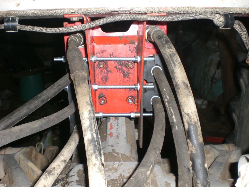
All was tightened together with threaded rods. The holed panel plate was turned upside down to make all couplers to fit. Those rubber blocks could have been made of PE-plate too.

Two pairs of double acting outlets, assistor ram, free return and single acting outlet from the selector valve (EXT2). Pump's feeds aren't combined. Double acting couplers use tandem pump's feed and single acting uses linkage pump's feed.
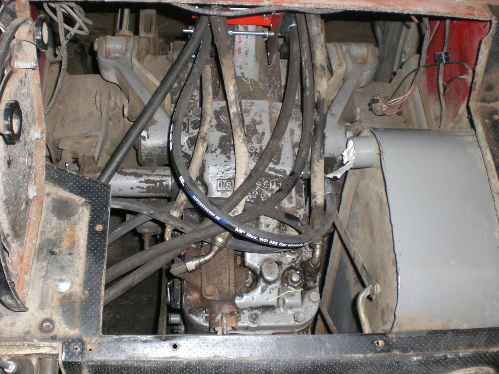
The hoses connected to rear panel, still missing the tube for fuel filling. Driver's seat and floor under it is then lifted in. The pumps were already tested when lift cover was off. The linkage works alright, maybe some setting will be done later via right side cover.
Main page
MF565 hydraulics
MF590 hydraulics