Massey Ferguson 590 pics and hydraulics
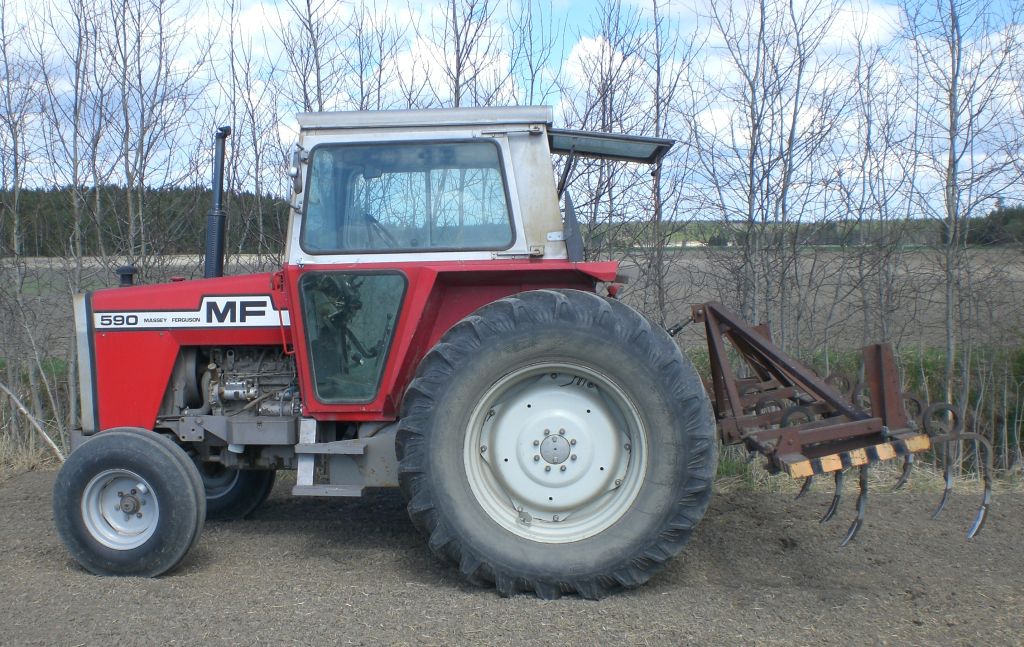
Massey Ferguson 590 made in France 1979 with cultivator.

Cross-sectional view of Massey Ferguson 500-series tractor. This is taped 565, but is actually 590. 565 cabin and hood are about 8 cm closer to the engine and gearbox than in 590 or 575. Picture is taken from a brochure of Hankkija, which was MF dealer in Finland.
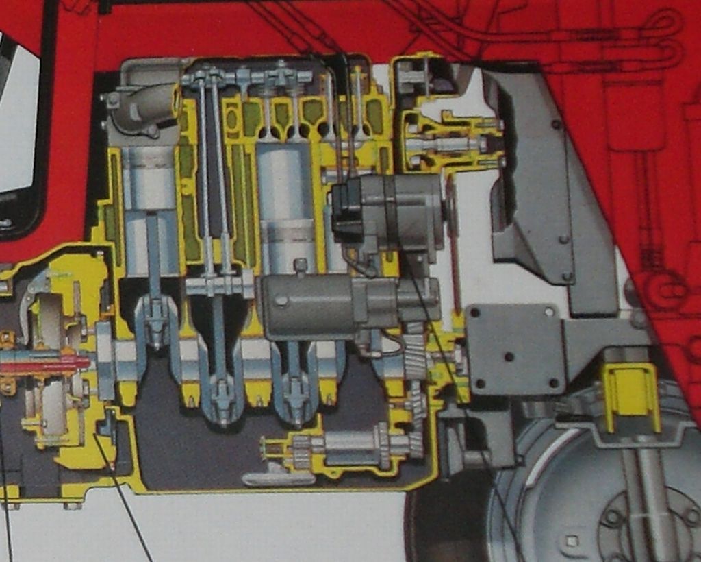
Unlike 565 and 575, model 590 has extension pieces between engine and front axle housing to make tractor 2,5 inch longer. You can see them under black line. The alternator has two legs, in practice has been only one what I've seen. It can come loose sometimes. Under the alternator is the pump for hydraulic steering system with integrated small tank. It can be replaced with MF300-series tandem pump as presented in my MF565-project page.

In this picture the tractor drive transmission line is colored red, except Multi-Power quick gear wheels are green and orange. Power take-off line parts are colored blue.

That red double gear wheel on the pinion shaft is actually part of the PTO-line (Power take-off). It reduces PTO rotation from 1000 to 540 rpm. PTO speed can be chosen by two different PTO shafts. There is no ground speed PTO, no room for it's gear on the pinion shaft. In Finland this tractor would normally have Ylö made tow hitch and separate locking pieces in the top link.
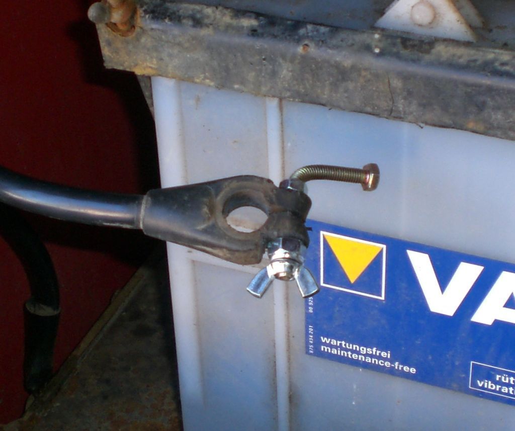
I made easy to fasten shoe for battery ground pole using bolt and wing nut. I first tighten the wing nut and then the bolt to make it even tighter. No tools needed.

Not to live terminal to avoid accidental short circuit and fire or other damage.

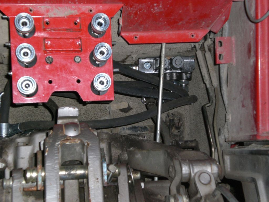
I installed in my Massey Ferguson 590 a double-acting valve table made by Walvoil with two pair of hydraulic outlets. The mounting of the operating levers was turned upside down. You can also see table's adjustable pressure relief valve. This valve block has half inch ducts and I had to enlarge the ready made hole in the cabin wall. This tractor had auxiliary pump, but it wasn't connected anywhere.

Block is bolted on downside of cabin's floor. Hose on the right is return (tankline) and on the left pressure inlet hose from the auxiliary pump. That long nut like thing is non-return valve, which is needed, because I lead linkage pump's output feed to this table too. To use linkage pump's flow one must adjust three-way selector valve and set the linkage lever to constant pumping position. I applied tar between floor and block to prevent rust. A Finnish specialty for British machine?
Originally these tractors have Kontak sectional valve tables if assembled.
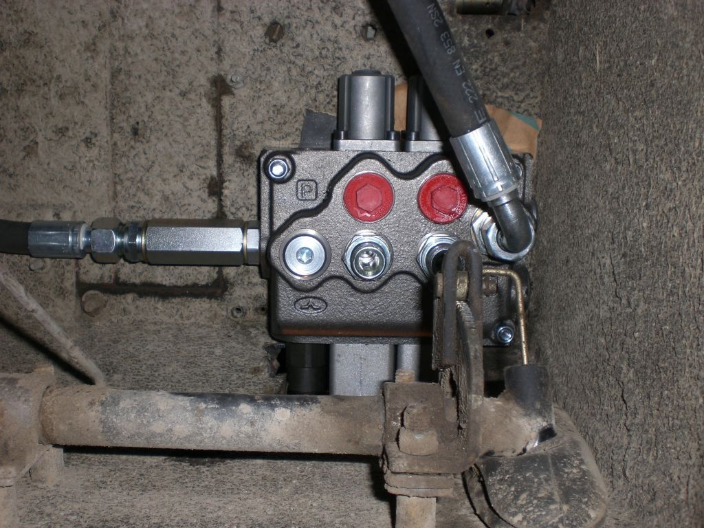
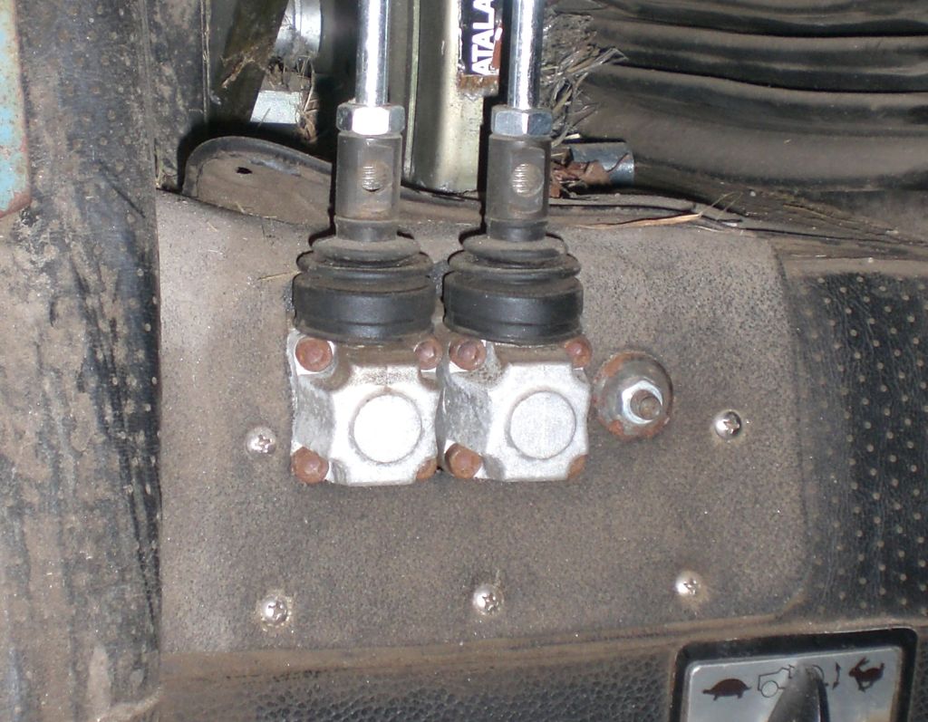
Seen from below. That plugged hole between P (pressure) and Walvoil logo is block's alternative pressure input. There I will fit non-return valve and hose from the EXT2 output of three-way selector valve in order to benefit linkage pump too in auxiliary hydraulics.

Added hoses to quick couplers in the back panel. I was partly using banjo connectors, which are not obligatory.

Auxiliary pump's pressure output and return pipe (tankline) come out through a round hatch on the left side and then up between tractor body and fuel tank. These have JIC-connectors that were previously connected with pipe loop meaning that auxiliary pump was not in action. I used a T-connector in tankline (bigger pipe) to add a quick coupler for free return in the back panel. Hidden behind the hose is a hole connected to internal lift cylinder. I'm using it to add a coupler for auxiliary lift cylinder.
The plug seen in picture is in selector valve (EXT1 port). I'm taking out linkage pump's pressure from EXT2 port on selector valve's right side. When lever is wound to EXT2 position, linkage is paralysed and pump feed goes to Walvoil table's pressure port. Linkage acts normally only in selector valves central position. Selector valve has also port for return (tankline) backwards from EXT2 hole.
Panel has quick couplers for 2 double-action outputs, tankline and auxiliary lift cylinder. Double output can be used as single-acting, if other outlet is connected to tankline with a hose. Works without it too, but may pump against relief-valve's pressure. More about fasteners in my 565 linkage page.
I should develop some kind of marking for those couplers to help memory.
I sealed the gap using some kind of insulation rubber found in the ditch.
Main page