The lift and auxiliary hydraulics on 100, 200, 500, 600, 300 series Massey Ferguson

The Ferguson System hydraulic 3-point lift levers and quadrants on a Massey Ferguson 590 tractor. Nearest the seat the position control quadrant. The lift arms move on the same direction as the position control lever. When the lever is rear (right), the lift is down. When the lever is moved towards center of the quadrant, the lift arms rise. Near the quadrant bend is the implement transport position and over the bend the constant pumping (blue) sector. On constant pumping the system pumps at full pressure against the relief valve and the lift cylinder. If the pump output isn't routed to some other use with the 3-way selector valve, don't leave the position lever on constant pumping. An exeption to this is if the outer lever alias the draft control lever is used instead; It's operating direction is opposite to the position control lever.
So nearer to the mudguard is the draft alias depth control quadrant; the lever is usually rear as in the pic. The draft control lever is used for example in ploughing. Moving this forward (left) lets the plough to get into the soil and the 3-p lift reacts to the push and pull on the top link and keeps the plough in the right depth though the tractor tyres would sink in the soft ground. When the lever is moved rear, the plough rises as high as the position lever is set and the top link push or pull sensoring doesn't affect. When the draft control isn't needed, I use special locking plates on top link bracket to reduce innecessary stress on sensor.
The quadrants are with adjustable stops and the levers with spring loaded tension screws.
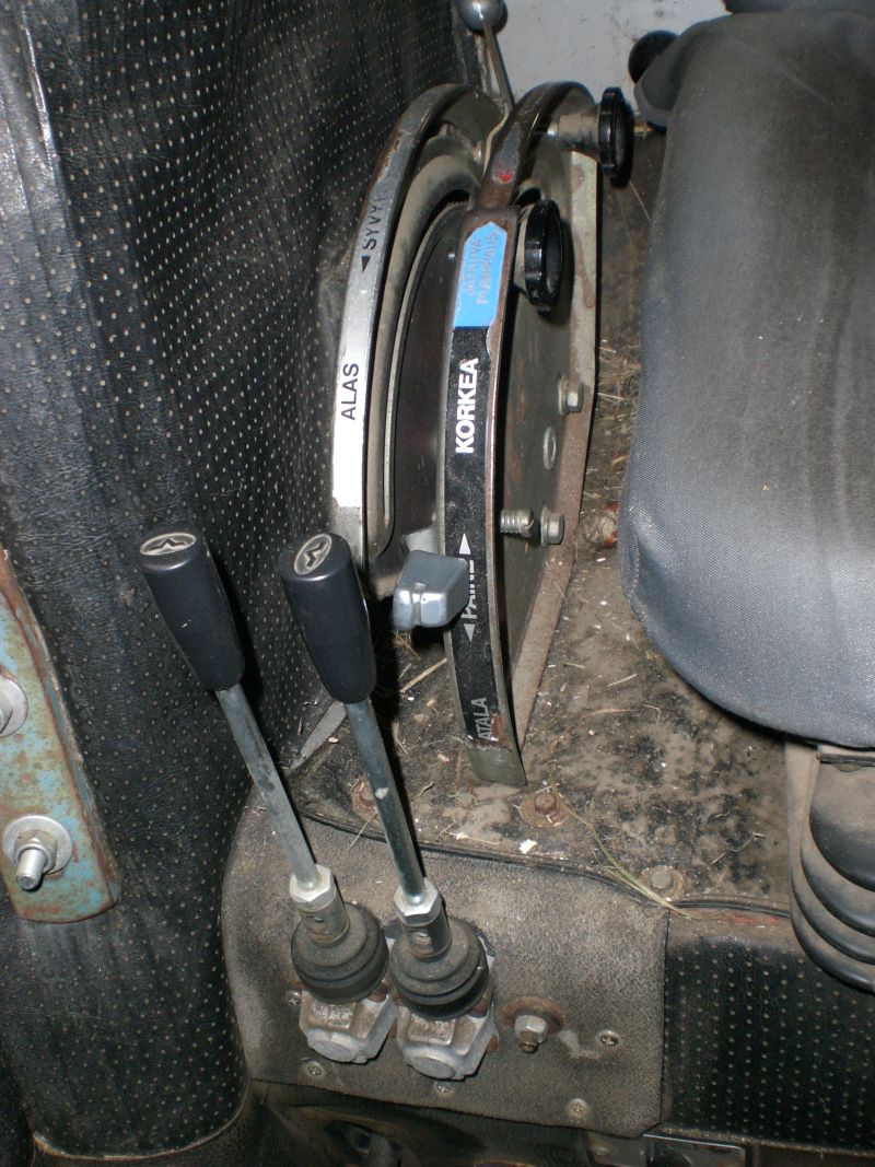
The position lever is now moved pass the constant pumping and to the pressure control sector. Pressure control is actually constant pumping on adjustable pressure. The lever front down the pump gives about 7 bar pressure to lift cylinder and when moved upwards the pressure increases linearly to about 210 bar, independently of the lift arms position or top link push-pull. With high enough pressure the lift rises on top position. This is better to find out with some more pleasant way than being between the tractor and the implement. The pressure control is originally ment to transfer weight to 2WD tractor back wheels with the aid of a special coupler or chain between the three point lift and the trailer drawbar. Could be used on many other purposes, but is a bit forgotten mainly because of 4WD and more modern tyres.
The pressure control could be used to lighten linkage attached or even towed machinery. And it could rotate a hydraulic motor with adjustable moment or the motor could brake on adjustable moment. On braking the return line should be below the oil surface.
On front the levers for auxiliary hydraulic outputs. Originally this tractor should have Kontak spool valves, but this 590 I installed an universal type Valvoil valve block.

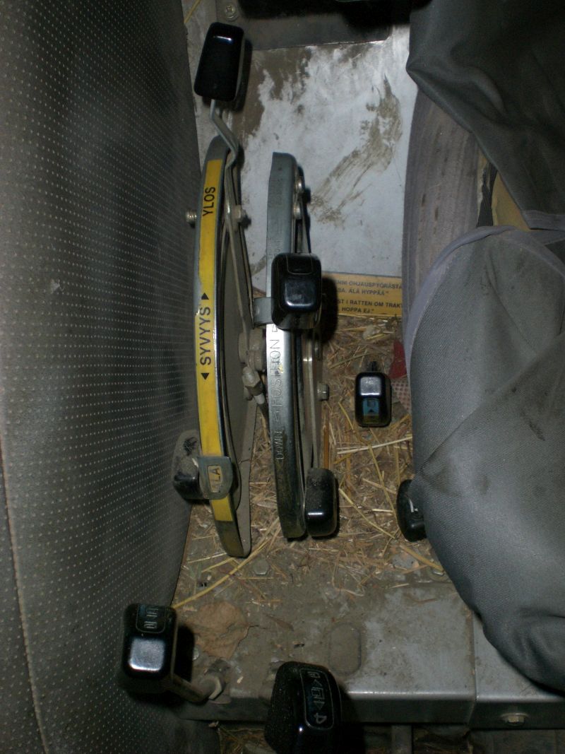
This 1965 Massey Ferguson 135 has the similar functions; Position control, transport, constant pumping and pressure control sectors on inner quadrant and the draft control on outer quadrant. On central housing's left round cover there's the dipstick for common hydraulic and transmission oil and also the response control lever, that affects to linkage's sinking speed. On later models this has often a broken linkage from cabin, so better check here underneath. On top of the lift cover a smaller cover, that can be replaced with a selector valve, that could steer linkage pump's output to external use. This 135 has only a linkage pump and one auxiliary fast coupler intended for trailer tipping etc. to which the lift cylinder pressure is connected. When tipped the lift arms rise before the trailer tipping cylinder moves. I have used this with the position control lever by moving it to transport or constant pumping to tip and hen back down. By the book the position control lever is moved to constant pumping and then the draft control lever is used to raise and lower, propably more accurate this way.
I have that similar "tipping output" installed in my 565 and 590. An assistor lift cylinder for my heavy seeding machine is coupled to this output, because the pressure is the same as in linkage's cylinder. Also in this output I've had the plain pressure cauge to see the internal pressure. For example in my MF 590 with centrifugal spreader I get 30 bar with empty spreader and 130 bar when loaded with 1000 kg of fertilizer. Now every 10 bar pressure drop tells me that 100 kg of fertilizer has gone to the field. Helps a lot.
That small cover can also be replaced with a special valve block and there's not need for separate pressure and return hoses. This can also be used to lift and lower the 3-point linkage, but the original linkage controls don't work and the levers on quadrants are skipped over. So the linkage gets down, if the lift cylinder piston rings leak.
The linkage pump is rather similar in all of these Fergies; Also in this 1990 model MF 390. The pressure control is left out. The lift arms are down when the position lever is on front and the arms rise when the lever is moved upwards. Constant pumping is on quadrant's back. Can be like this on older models too when the pressure control is missing. Half of the response control knob is visible under the seat. On front the auxiliary hydraulic's levers; The Kontak valve block is on the back of the cabin. This 390 is with a front end loader. Often the hoses to FEL are connected parallel to the auxiliary outputs of the Kontak valve and the FEL hoses are with cut off taps, that are closed, when the auxiliary outputs are in use. This tractor's loader has it's own valve block with a serial connection to original Kontak valve table. More about MF 390 hydraulics in own page.

Kontak levers in a Massey Ferguson 699; The blocks are behind the cab wall as in 500-series. Below the levers the turning knobs to choose single or dual hydraulic action. On the right the response control alias lift arms sinking speed. Photo by EK.

Kontak sectional valve table in 699. In this case the pressure- and tankline are with a bit odd connectors, but can be replaced if leaky. Photo by EK.
If the linkage pump was the only pump in this tractor, the pressure line would come from the threeway selector valve, that would be turned out of the linkage (center) position. So the linkage is paralized, when the auxiliary hydraulics is used. In the Ferguson System the lift cylinder is straight connected to pump's output and you can't "steal" oil from the connecting pipe, if you want the lift controls to work. More about this on the MF 565 linkage repair page.
So you must turn the selector valve between the linkage and auxiliary hydraulics positions, if both are used. The only real help is another pump for auxiliary hydraulics. For example inside the central housing of this 699 there's a dual element auxiliary pump. You can use the auxiliary hydraulics with it and also turn the linkage pump along, if more flow is needed.

The auxiliary pump pipes on the left side round cover as seen from the underside of 699. The larger pipe on the left is tankline (return), this is still in the same spot in the 300-series. The right one is the pressure pipe. MultiPower-Fergies can be equipped with the plain MultiPower (MP) pump, that can't serve oil to the working hydraulics. The Auxiliary pump is a tandem gear pump with the MP unit and the other unit for auxiliary hydraulics. The axiliary hydraulics works with the same oil, that is used for transmission lubrication, but in 600-series the steering still uses own reservoir and pump. Photo by EK.
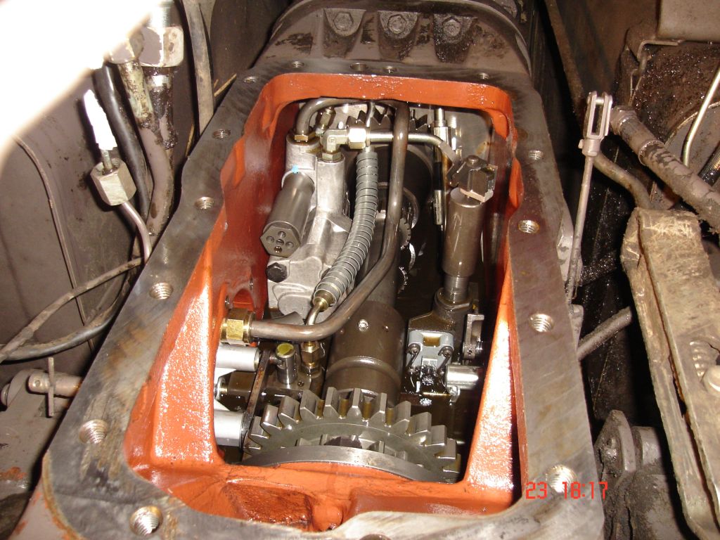
The Auxiliary pump inside the transmission housing. The linkage pump is hidden below the oil level. The linkage pumps stayed rather similar from 35 to 300-series (and probably to 4200,4300?). The pump is part of the Power TakeOff transmission line and output varies along the rotation speed. Rotation can be 540 rpm (Standard, 540 and ground speed PTO) or 1000 rpm (High Flow, 1000/540 PTO with interchangeable shaft). Then in Massey Ferguson 300-series the auxiliary pump was transferred to the side of the engine and the steering used the same transmission oil too. Photo by EK.
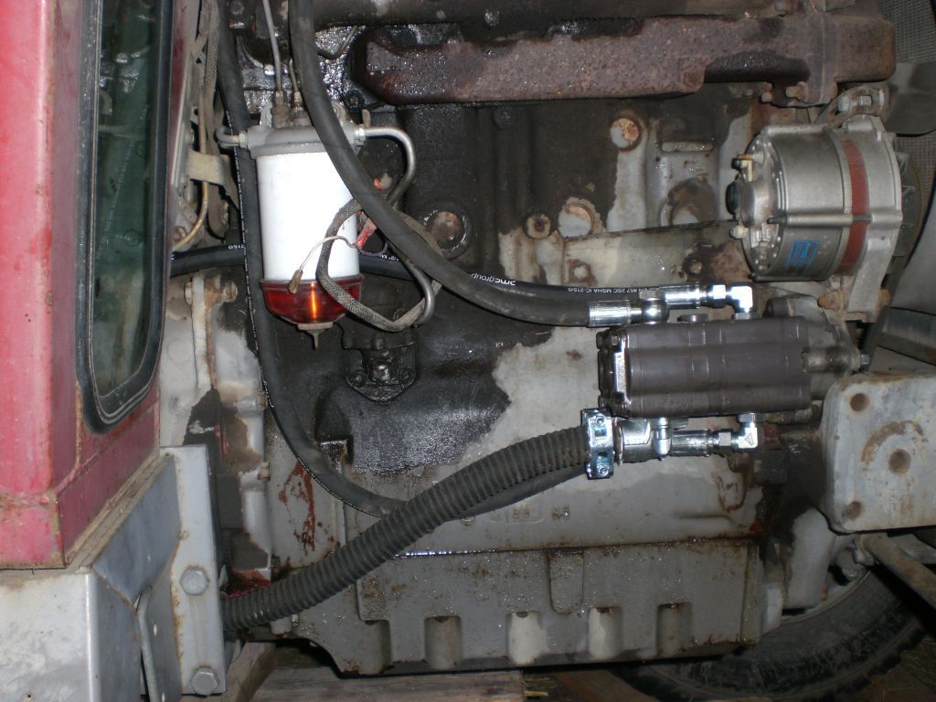
It's possible to build the 300-series type system to older Fergies with the Perkins 4.248, 4.236 or 4.212 engines by replacing the steering pump with a 300 style tandem pump. I installed a 390 pump to my MF565. The pump takes it's power from the engine camshaft gear.

My pump gets oil from the linkage pump's suction strainer maintenance opening. The Massey Ferguson 595 can have a pipe here for the outside located strainer or filter.

Also this Kauko's Massey Ferguson 590 was fitted with a 390 tandem pump and the suction is trough the right side round (dipstick) cover. This fits also in the older models without the opening in the bottom and the suction line is in a very safe place. Photo by Kauko.

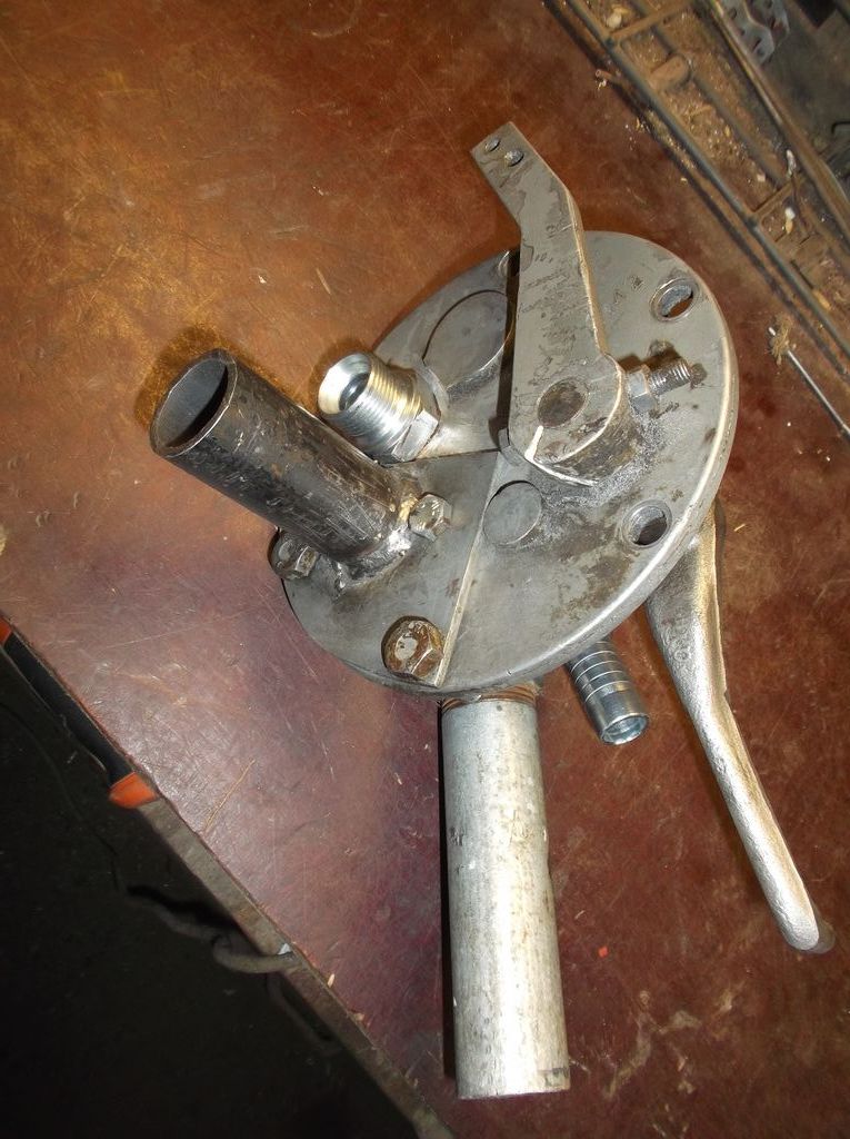
Here a MF 265 with a PTO pump, that nic "Ferkku" installed in Finland. I thank him for the photos and the whole Ferkku System concept. This pump is removed, when the PTO output is used for other purposes. On the left an assistor lift ram to increase the lifting power.

The intake oil is sucked through the left side round cover. The return hose comes here to the same point than in the Auxiliary pump Fergies including the 300-series. The fuel tank would be here in a way in 500 and 600 series. That suction hose could also go towards the tractor front and with a front mounted pump the PTO shaft wasn't occupied. Considering the 300 style pump this cover is on the wrong side of the tractor body, but maybe the suction could be built on the right side cover too. Photo by Ferkku.
The suction pipe is made of water pipeline parts with the inner diameter of one inch. Photo by Ferkku.
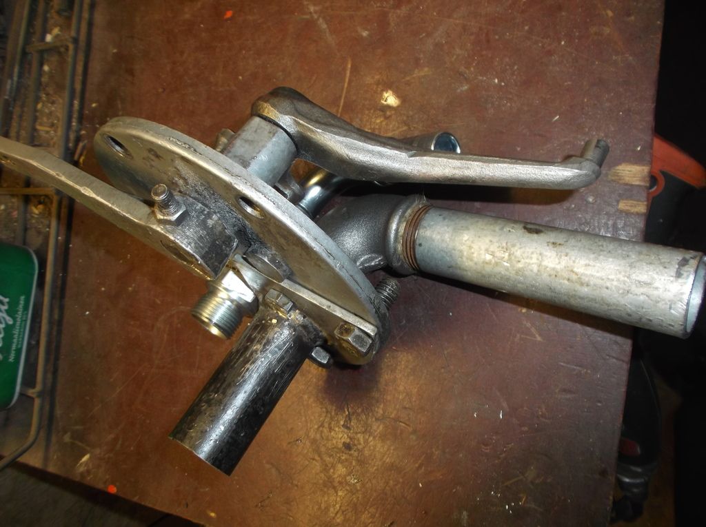
The fitting must be precise to give the space for the PTO coupler to turn and to make the cover installation possible. This don't fit with the hydraulic PTO coupling, IPTO. Photo by Ferkku.
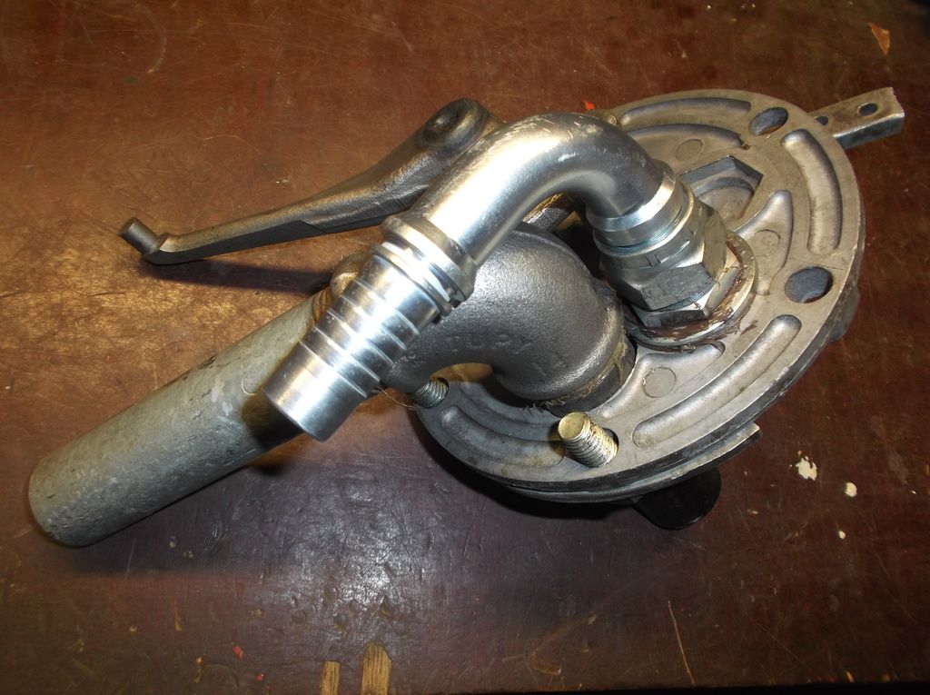
The return oil gets below the oil level and the suction is near the transmission housing bottom. No suction strainer. Photo by Ferkku.
Then there are two transmission oil draining plugs, that can be used for tankline. Some have used them even for suction.
You can also install a front mounted pump on Massey Ferguson, the pump takes power of the splined flange fastened to the pulley on the crankshaft end. Over the front axle there's a hole through the front axle housing, where can be placed a straight shaft to the pump. The housing is with a ready made place to fasten the pump and these are installed at least in industrial model Fergies. On sale I've seen at least rather large about 100 l/min pumps and ready made parts to join these. These pumps often use their own hydraulic reservoir.

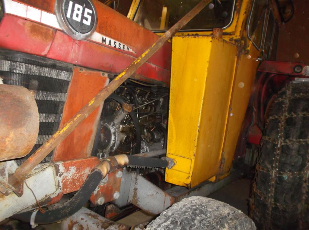
Here a Cessna front mounted pump on a Massey Ferguson 185, that has a timber crane mounted on the cabin roof. The pump drive shaft is with 11 to 15 splined end, depending on the size of the pump. Photo by Ferkku.

The crankshaft pulley with the bolted on flange for the pump shaft. The shaft is splined or with a counterclockwise sparse thread. Photo by Ferkku.
This pump is with it's own oil tank and filter in the return line. Photo by Ferkku.