Massey Ferguson 390 hydraulics and gear shift repair
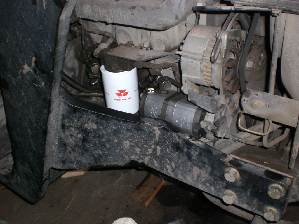
Massey Ferguson 390 new tandem pump was installed, when tractor was in two pieces. Also installed a new return filter that's in low pressure circuit for steering and hydraulic switch stacks. That mounting frame of the James front loader is made of rather thick tin plate and may slow down the assembly.
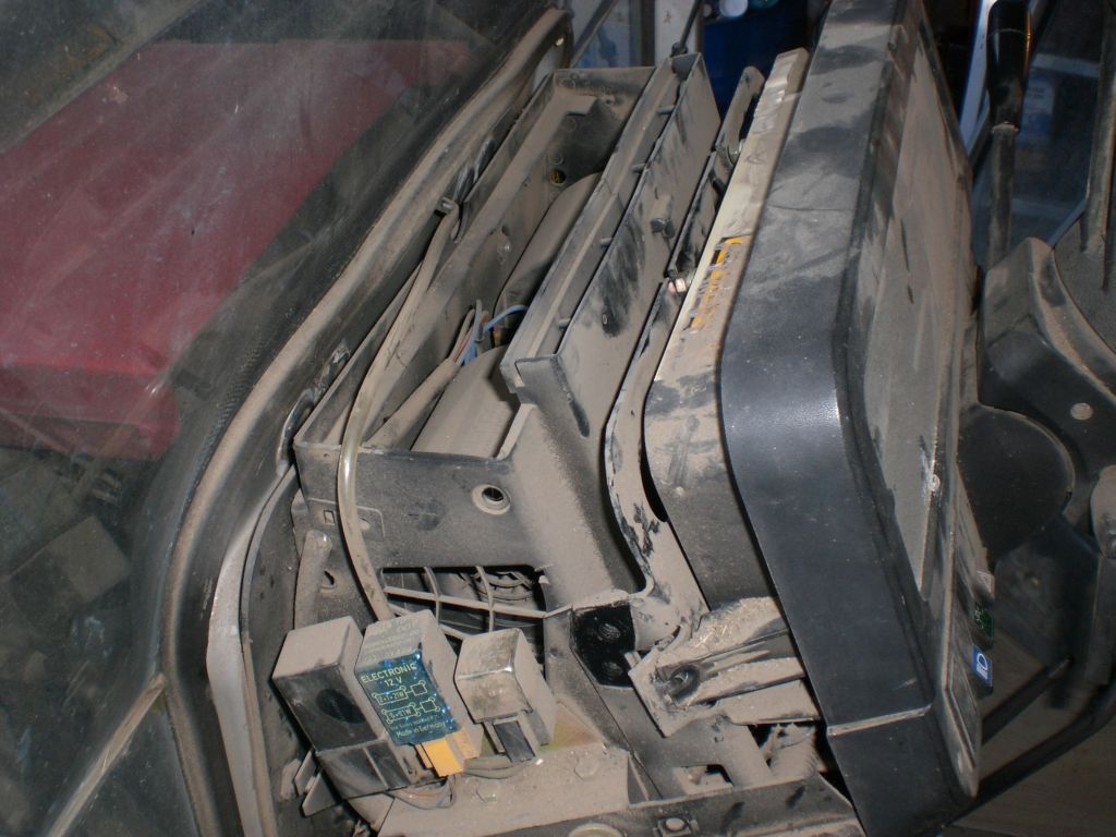
Pump's position on the side of the engine and filter's leg. Filter unit has sensors that should indicate when stuck.
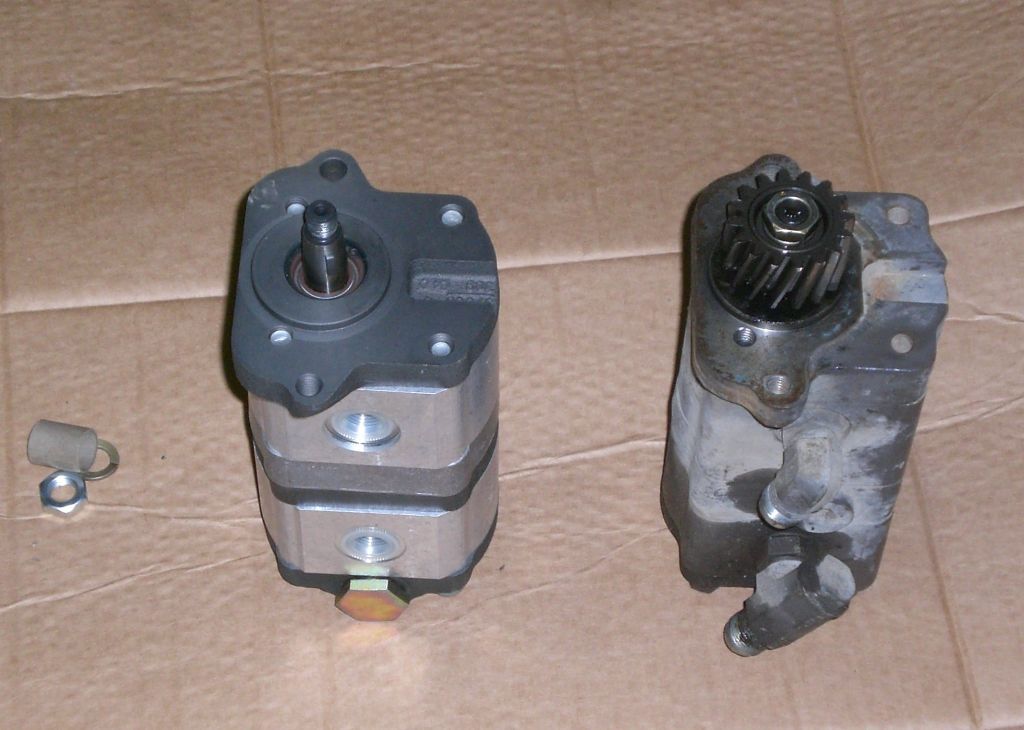
The pumps, new and old. Used pump was fitted to replace Massey Ferguson 565 steering pump. That's why I had to buy a new drive gear wheel, MF part number 1695001M2. Search by number shows the gear available in several places nowadays. Tandem pump repair here.

There's separate pump sections for auxiliary and low pressure hydraulics. Auxiliary pump is next to drive gear. Low pressure pump has 3/4 inch (19 mm) suction hole for flange connector with 2 bolt holes of 40 mm distance. Suction inputs are connected inside tandem pump, though 2 inlet holes outside. 390 has different makes of pumps with at least slightly different volume per revolution value. Old is Sauer-Sundstrand and new Rexroth make.

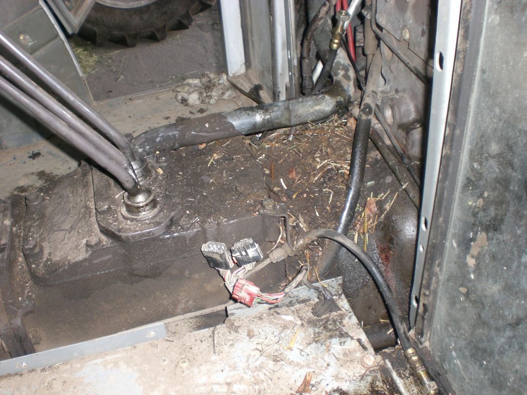
Year model 1990 MF 390 low pressure hydraulic circuitry as seen inside cabin;
front wall and orbi hoses removed. Low pressure pump section's output is connected to orbitrol's pressure input. On the outmost left
and right are the pipes 1. to steering cylinder with yellowish JIC-connectors. These are connected to orbitrol with hoses. Orbi's
return hose comes to T-connector 2. behind circuit's return pipe 9. T's other ends are the hose to PTO stack at the rear and the pipe
to oil cooler in front of radiator. Oil cooler's return hose 3. comes to bar connector manifold. 4. On it is sensor 5. for circuit's
pressure wired to alarm light on the dashboard. Connected to manifold is a pipe to magnetic valve 7. for differential lock inside front axle, pipe/hose leads there; Rear axle diff works with a foot pedal. Back of 7 very close to exhaust is connected a hose 6 to clutch housing, probably to lubricate the clutch shaft in the gearbox. Circuits pressure on points 2-7 is determined by spring loaded valve 8. Valve drains to return pipe 9. connected via filter to auxiliary pump section input. Aux. pump takes oil also direct from other input.
That's the way i see it. I wrote it down and loaded to internet, which still doesn't mean it's the absolute truth. Not far I hope.
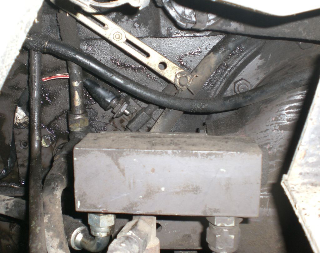
On the left side in front of the rear axle there's a manifold block, where auxiliary and linkage pump flows are combined when necessary. Linkage pump line from "selector valve" is in the middle and is enclosed with an one-directional valve. Should be an another steel ball between the T-connector and the block, that works as an one-directional valve on auxiliary (tandem) pump line, that's on the left. On the right end of the block there is auxiliary pump's relief valve, large nut hardly at sight in the picture. Relief valve's tank line on the right is connected to cross-shaped connector on the round cover on tractor body (central housing). Other return lines connected to this cross come from FEL's valve board (front end loader) and Kontak sectional valve table on the back.
In this tractor line (in the middle) for combined flow is connected to FEL's valve board, that has serial output, where the pressure is further led to tractor's original Kontak valve board on the back. FEL's board is with own relief valve, so we have extra pressure limiting in this tractor. The lift (linkage) pump's relief valve is on the side of the pump itself.
The system became familiar cause I opened some hoses to get access to leaking brake cylinder there behind. Then found out I must get some oil out in order to drop transmission oil level. I decided to start the engine and pump some oil clean to bucket. Because of one-directional valve oil flew from different line I've first expected. Suprisingly some oil came out from relief valve's tank line too, though back pressure was null. Also front loader has been lazy when driven auxiliary pump only without the linkage pump's combined flow. I decided to open the relief valve to see what it looks like.

The pressure relief valve taken out, this limits the (tandem pump) pressure to 180 bar as stamped on the nut and adjusted with the washers in nut's cavity. The copper gasket had broken into 15 pieces, that all were still in original position. Anyway some hydraulic flow was missed. I placed in a new 20x26x1,5 mm copper washer, that didn't fit very tight. Some Usit ring gasket could be better if modified a bit. The loader started move faster, which is best noticed when using one pump only. Checking this out is worth doing, if hydraulics are lazy. This is probably Bosch made valve, can be 2 other makes too.
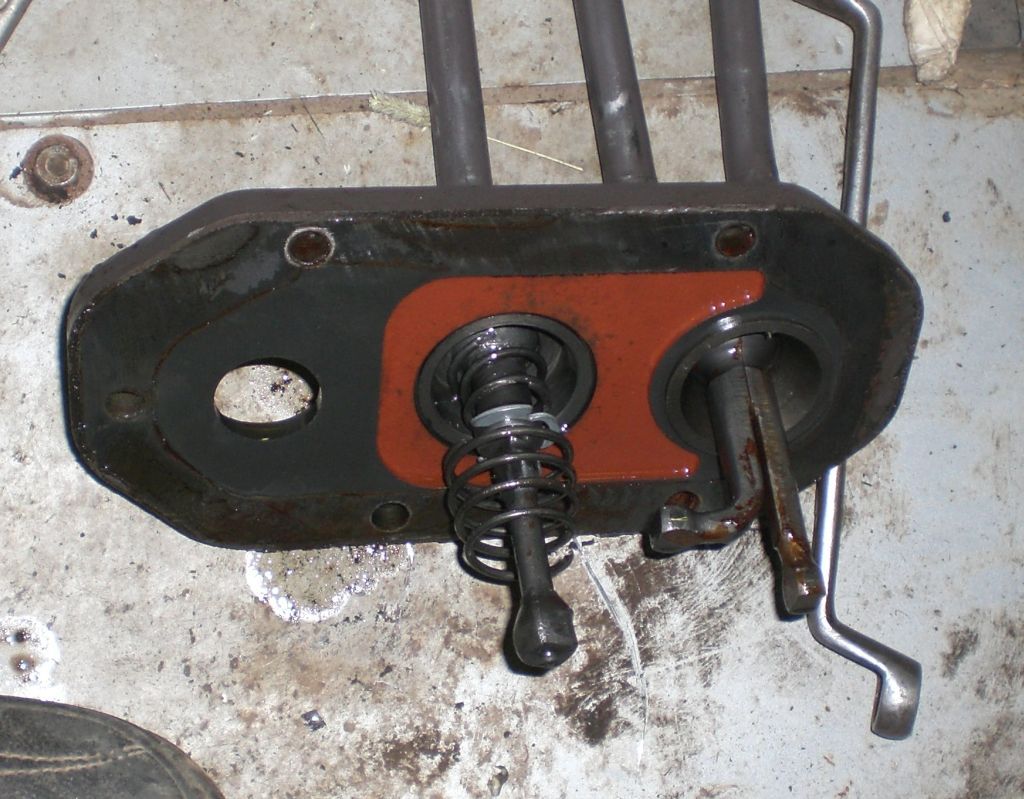
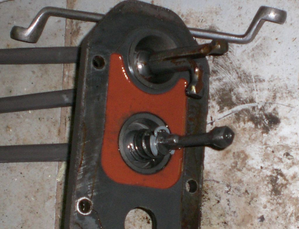
Gear stick stabilizer similar to older MF, conical spring had broken to two pieces and larger part had fallen through the ring pin so that I couldn't move stick to 2. and 3. gear slot.

The gear stick can be twisted away with it's bowl, but only downwards. The locking nut at the base is first turned open and locking pin through sift and bowl driven out. Now the bowl can be turned out with about 40 mm open end wrench. Anyway the cover and sticks package must be removed first, unless you only adjust the height of the lever.
At this point I assumed that it's necessary to split the tractor. Also the heater blower in cabin's front wall needed rebuilding. To release it inside the cabin seemed difficult, so I lifted the whole front wall outside to the yard.
In older MF to 500-series plug for common transmission and hydraulic oil fill inlet is here besides the gear sticks. In 390 inlet is moved outside cabin with that tube. In my tractor new position isn't much better, cause the inlet is behind front loader's frame. The tube also makes dismantling a bit more difficult, but don't prevent to lift the cover and sticks off.
The mouse family had found the gap between cabin and body a nice environment to live and had carried in all sort of decoration material with daily mail. Oil had also leaked pass the broken inner sealants. The wiring was there within making gap hazardous, if mouse teens were interested in electronics.

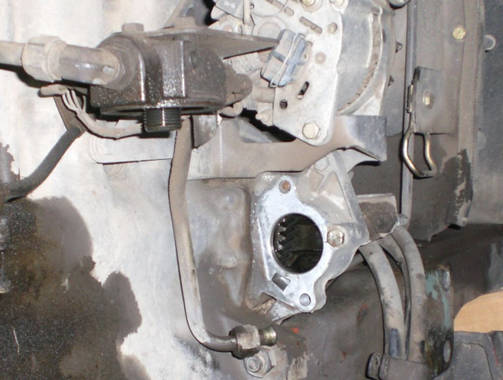
Cabin's front wall removed and rats driven out to neighbourhood. In the middle of engine-gearbox jointing is a bolt with 12-corner head in a difficult position to open. In front of it is auxiliary pump's pressure pipe to connections in tail, short pieces joined together. I replaced the pipe collection with a long hose straight to back, cause connectors leaked a bit and were not comfortable to tighten and open.
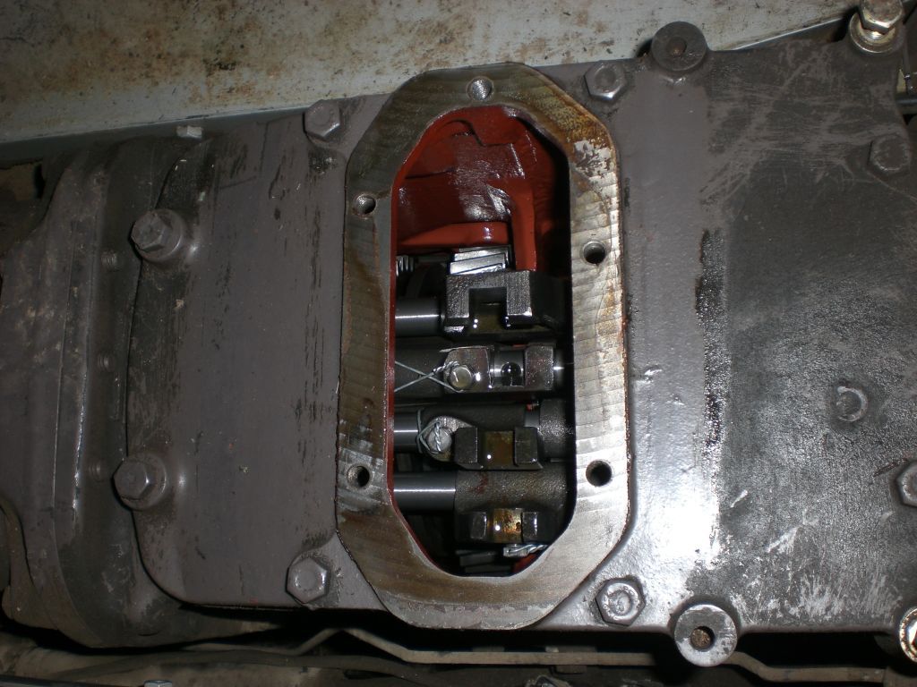
Synchro-Power gear slots. At the top 2. and 3. gear slot, then 1. and reverse slot. The next is Synchro-Power and the lowest is the multiplier gear 1:4.
Stick's lowest end engages 1. or reverse gear. The expansion higher on the shift engages 2. or 3. gears. The ring pin travels like a sputnik if not taken care. It must be small by outer diameter in order the shift to move freely, cause 2-3 gear rod is near it. Gear shift can be adjusted higher or lower by turning the threaded bowl.

The heater and cabin's front wall was separated with a crowbar.

The blower unit taken out. The lower of two speeds is achieved by leading current to motor via green resistor.

The blower motor and fans. The fans needed to be transferred to a new motor. I tightened the rotten motor to vise and pressed the bases of the fans to slide them out of axles, using a kind of bended steel rods. The plastic fans can be sunken to warm water to easen removal and installation if necessary. The motor is fastened to bed with a hose clamp. The bed has a spike that fits a low bore in motor to keep it steady. The new motor didn't have this bore, so I made some sort of bore for shortened spike. The fans must be set to axles as picture demonstrates and also the direction of rotation determined by the wire order must be correct. My match was good enough, cause the fans rotated freely and blowing was strong when tested.
The heater removal inside cabin is difficult, because there is not extra room in the cabin. The front wall fastening bolts should be removed and divide the wall from windscreen frame. There are some heater bolts almost hidden under windscreen and some heads of bolts are below sound insulation outside wall.
The cabin is Lo-Profile model. The heater rotates warm air inside, but don't take fresh air outside. There is fresh air blower at the roof with no heater. Cabin hasn't any outlet channels for air, so the lower part of rear window should be kept a little open in order to ventilate air. Otherwise the roof blower can't push fresh air in, cause cabin is too impermeable.

Massey Ferguson 390 position control lever to adjust linkage while standing outside cabin. The lever can be fastened to right mudguard. People have had accidents with this kind off lever, cause pushing it makes the linkage to go all the way up. On the safer incremental type lever version, the linkage makes only a short lift on each push.