Massey Ferguson 500-series linkage pump repair

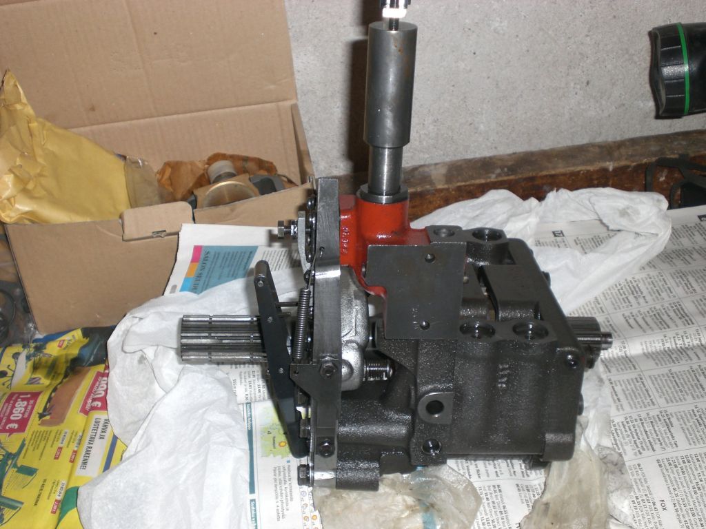
Massey Ferguson 565 linkage pump taken to the table. It's a boxer type 4 cylinder piston pump. The pump shaft is also part of tractor PTO transmission line and rotates 1000 rpm at engine speed 1690 rpm. The shaft heads have 21 splines similar to that common in 1000 rpm power take-off stumps. On pump sides there are holes for fastening pins.
That nearest lever affects on linkage drop speed, adjusted with round side cover lever. That up showing cylinder thing is for pressure control. This is integrated to the pump, in older models (100-series) pressure control devices are more attached to the lift cover.

Suction strainer should be on the left, now taken off. It can be removed via an opening at the bottom of central housing, covered by triangular plate. The linkage's control valve is integrated to the pump and governed by a lever in front, a roll in it's head. The pressure control device directs this lever by a hook. Pushing that roll rejects the flow in pump's inlet and also drains outlets oil back to central housing's oil reservoir. In position seen in picture the lever allows pumping at full power.

This end is towards tractor front end. MultiPower or Auxiliary pump fastening parts and driver gear set are here, this tractor don't have them. I tell more about them on my Massey Ferguson auxiliary pump page. This MF 565 I installed a 300-series tandem pump to engine side instead of the original auxiliary pump.

The pump camshaft moves a connecting rod that rotates control valve spool back and forth to keep the spool sensitive to move left and right as seen in picture.

The suction inlet and control valve lever taken away.

The front end can be seen marks of wearing made by the camshaft pressing. Apparently a too long drive shaft in PTO can harm the pump too, have tried to avoid such though.

Cylinders and pistons with rings. Brass metal blocks act as connecting rods of the pump.

The rear end and valve spool hollow part.

The control valve and worn front end.

The larger holes are for pump suction and smaller to let oil drain from outlet and ram. The spool's heads have slots to make working smoother.

In the head of spool rod there is a very small locking ring, diameter approx. 3 mm. Hole in that pipe is four squared.

The valve assembly, the new valve lowest. That long spring pushes the spool to the right. The rod is four squared in order to transfer rotary movement to the spool. Rotation makes the spool to slide sideways, which removes static friction of lengthwise movement. In accordance with my habits I managed to buy a wrong kind of valve, but fitted it anyway. Added a home made washer to make square parts meet.

The new cylinders and pistons put together.

The shaft and new brass blocks are then installed. The brass connecting rods must be in right places in order the pump to rotate freely. The valve rotating rod gets it's movement on the other brass block.

The suction end installed.

The valve with extra home made washer and ordinary small ring socket.

The pump assembled, the strainer missing. In front pump's straight pressure pipe to selector valve. The sealing rings on ends are often the reason for missing pressure, easy to renew. O-rings are with white support rings.
Back MF565 linkage
300-series hydraulics to MF 565
Main page