Massey Ferguson auxiliary dual element pump
These photos are of Massey Ferguson 699 tractor , but I think my MF 590 with auxiliary pump is very similar inside the central housing, where the hydraulic pumps are. Photos on this page are by Esko Käkönen, I thank him very much for the possibility to use these pics and write the page.

The existing auxiliary pump on MF can be reasoned on pressure and return pipes, that come out through left side round cover. The larger pipe is return and probably the best target to connect extra tank lines.

The outputs as seen under the central housing. On side cover also shaft and lever for PTO switch-on and 590 would have a smaller plugged output for measuring PTO stack pressure. This has a pipe, maybe for warning light?
At least on older models there can be plugs on these outputs and the pump isn't used, if it exists. In my MF 590 the pressure was pipe looped to return, so the auxiliary hydraulics was not in use.

Fuel tanks under cabin on both sides of tractor body on 699 and 690. 675 would have only one tank on the left. The seat and cabin's upper floor is removed and also the lift cover lifted away.
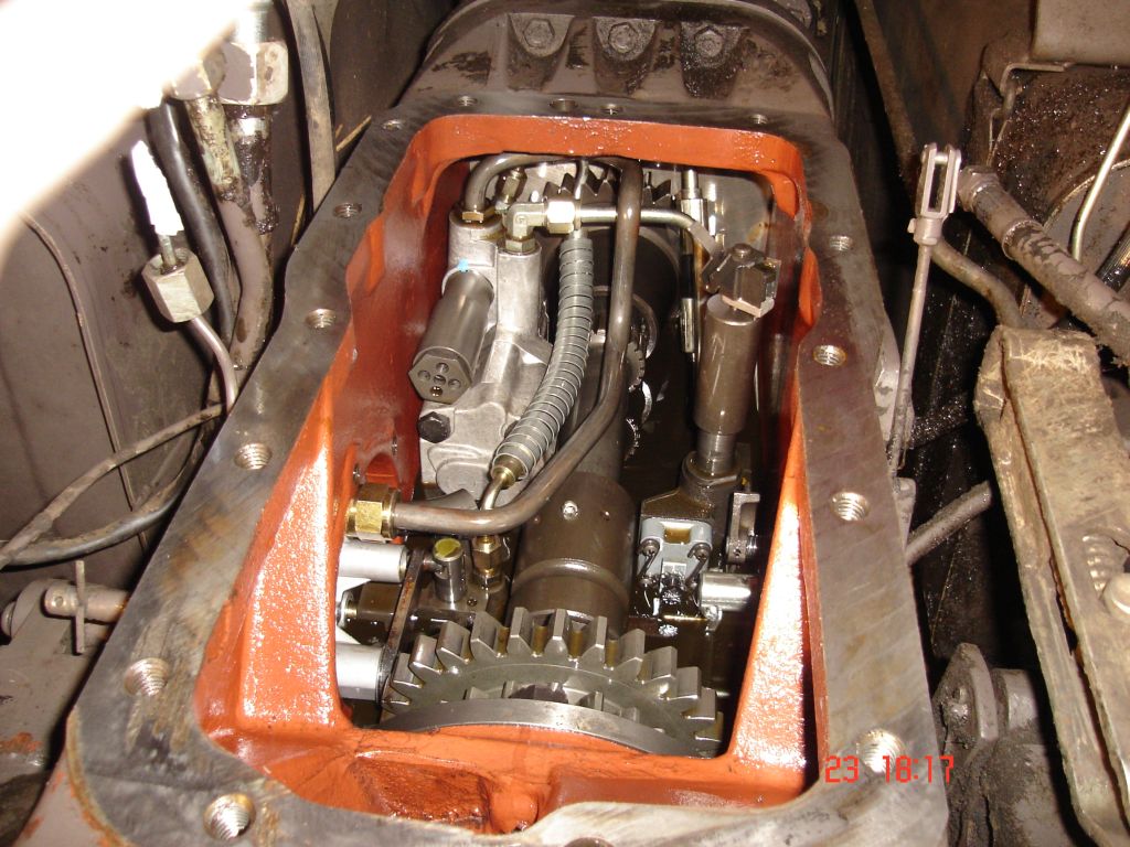
The view inside the central housing. The auxiliary pump is a dual element hydraulic pump, which has two sets of pumping gears. One set feeds external hydraulics and other set lower pressure oil for internal use.

When there seems to be something wrong with the MF hydraulic system, a good way to start is to take off the right round side cover. On older models with Mark2 3-point rear lift system that roll on pump's lever needs to be taken off before removing the lift cover. In this Mark3 model system it's not necessary any more, but through opening you can see possible leaks and how lift pump controls work while the engine is running. With some know how you can also use the rear lift by moving the levers between lift cover and pump. As far as I know Massey Ferguson tractors on 200-, 500-, 600- and 300-series are with Mark3 pump. There are also older MF models with Mark3 starting on serial numbers 165: 136610, 168: 256093, 185: 320846, 188: 361108 and 188-4WD: E175005.
The double gear wheel on front is for reducing Power TakeOut alias PTO shaft rotation speed from 1000 rpm to 540 rpm.
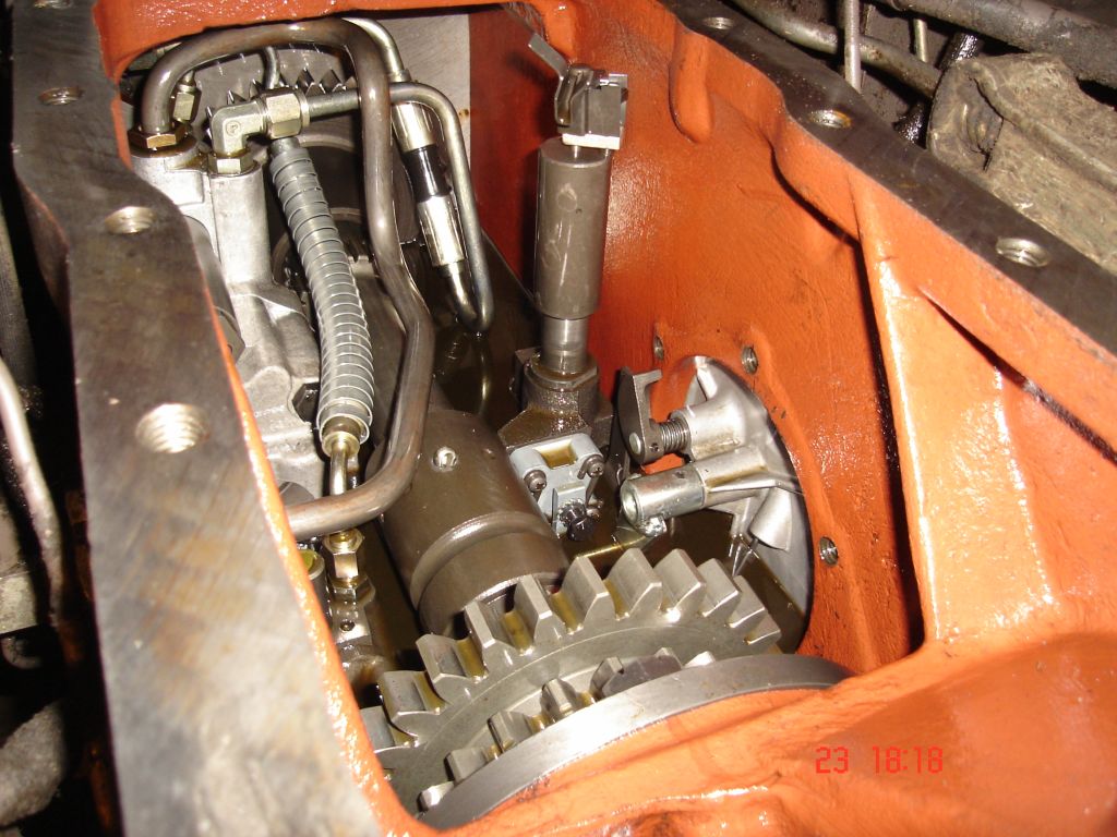
The oil level must be lowered before opening the side cover. But the dipstick is on the cover, so it's easy to see the right level. When reassembling the lever attached to lift cover should find it's place at the back of the pump's lever with roll. This can be checked on the side cover opening. When lowering the lift cover on my MF 565 linkage repair I had side cover closed and pump's lever pulled close to pump with a snare. The middle of the snare looped up the roll and heads were led behind the pressure control valve and then outside the dipstick hole on side cover. After lowering the lift cover I got the snare off by pulling on the other end. The pressure control valve is that tower on the right. It leaks oil when engine running and that's normal.

The splined sleeve slides right after the cotter pin on it's hole has been removed and the drive transmission shaft can be lifted out. The sleeve has a thinner place to break before anything else more expensive parts of transmission.

The auxiliary dual element pump over the lift pump, relief valve for the external hydraulic on the side. Rigid pipe is the pressure line from pump's auxiliary hydraulic part to the left side cover. I call the low pressure part MP pump, because it would be for MultiPower, if this tractor had such. Here it serves oil to hydraulic PTO stack (IPTO) and 4WD stack. The spiral covered hose leads MP pump's oil to PTO stack and the pipe-hose-pipe combination to cooler and filter outside.

The drive transmission shaft is now removed as well as pressure pipe to side cover and pressure control valve's top part. To get the lift pump out it's necessary to split the tractor between central housing and spacer block on tractor body. This because of gear wheels of the 1000/540 rpm lowering gear on PTO line, if nothing else.
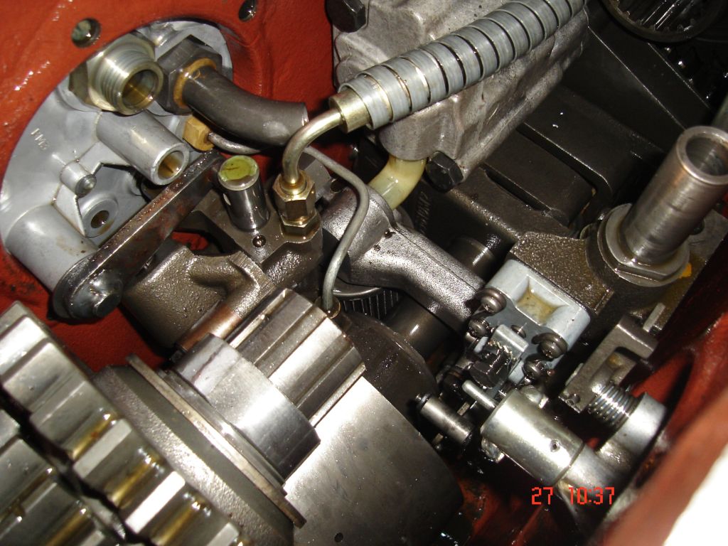
On the side cover curved pipe stump for return oil and shaft for PTO switch on, moves the valve, that directs hydraulic pressure on the PTO stack. The auxiliary dual pump intakes oil through curved plastic pipe on the same suction strainer as the lift pump.

On the right side cover there's shaft and cam, that puts the lift pump on constant pumping, when the lift pump output is combined to auxiliary hydraulics by twisting the lever inside cabin. The cam presses the lift cover lever backwards and spring force makes pump's lever to follow. 600 and 300 series tractors have this action, in 500 series you have to separately move the position control lever on constant pumping part of quadrant. The other shaft on the side cover with eccentric half moon is for adjusting linkage's lowering speed.
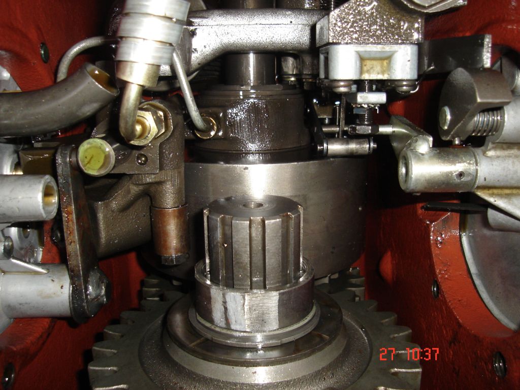
The PTO brake is visible somehow.
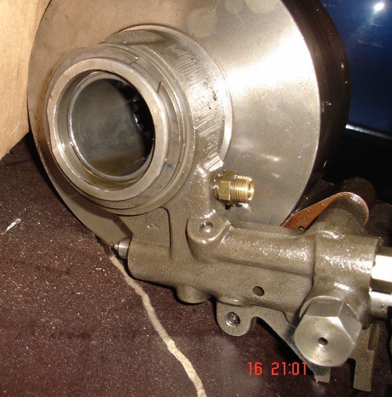
The separated PTO stack including valve, that gives pressure oil to PTO switch on or to braking cylinder, that forces the brake shoe against stack's outer wall.
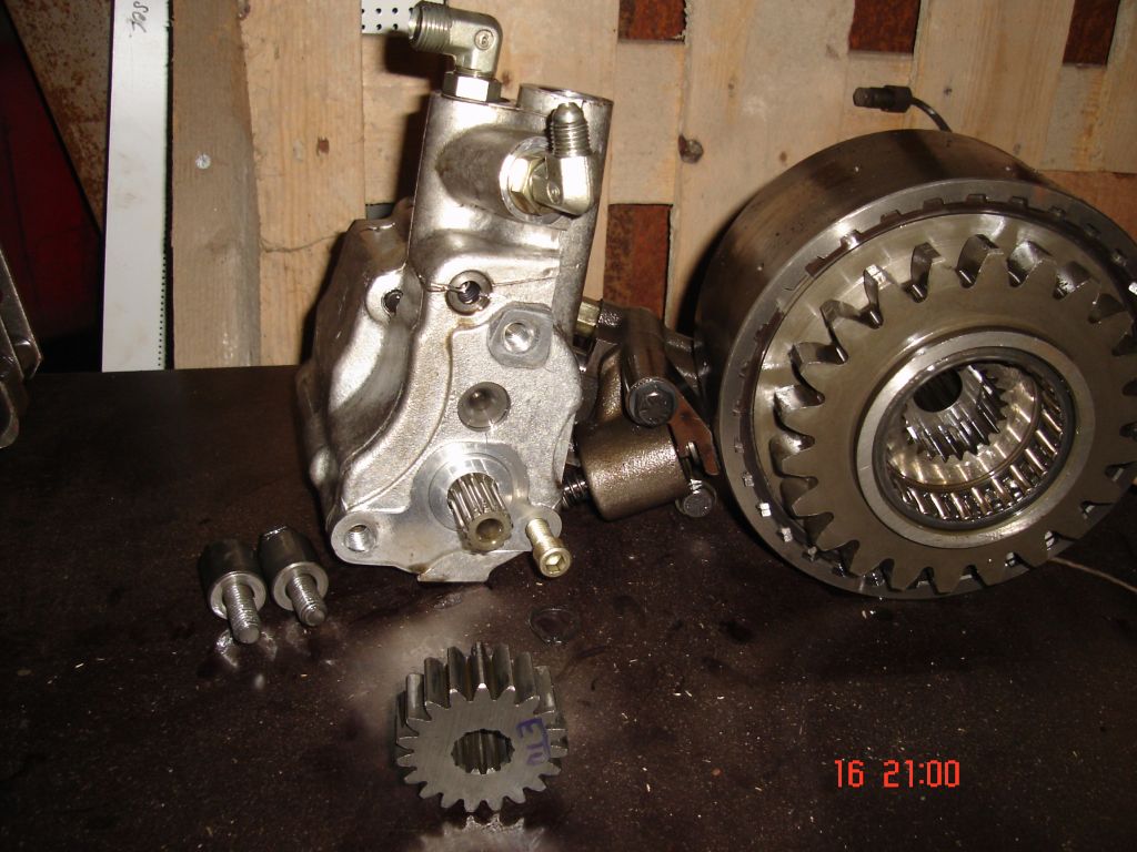
Auxiliary pump with drive gear and PTO stack. Two different kind of PTO shaft can be used. 1000 rpm PTO shaft splines meet the splines inside stack and 540 rpm shaft splines meet the splines of other gear on PTO lowering gear set, not in picture.

Auxiliary dual element alias tandem pump.

The linkage pump taken out. It's a part of PTO power line and fastened to central housing's walls. The auxiliary pump is attached to this with plates and is driven by the gear set between the same plates.
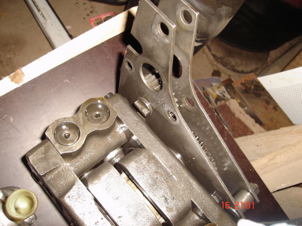
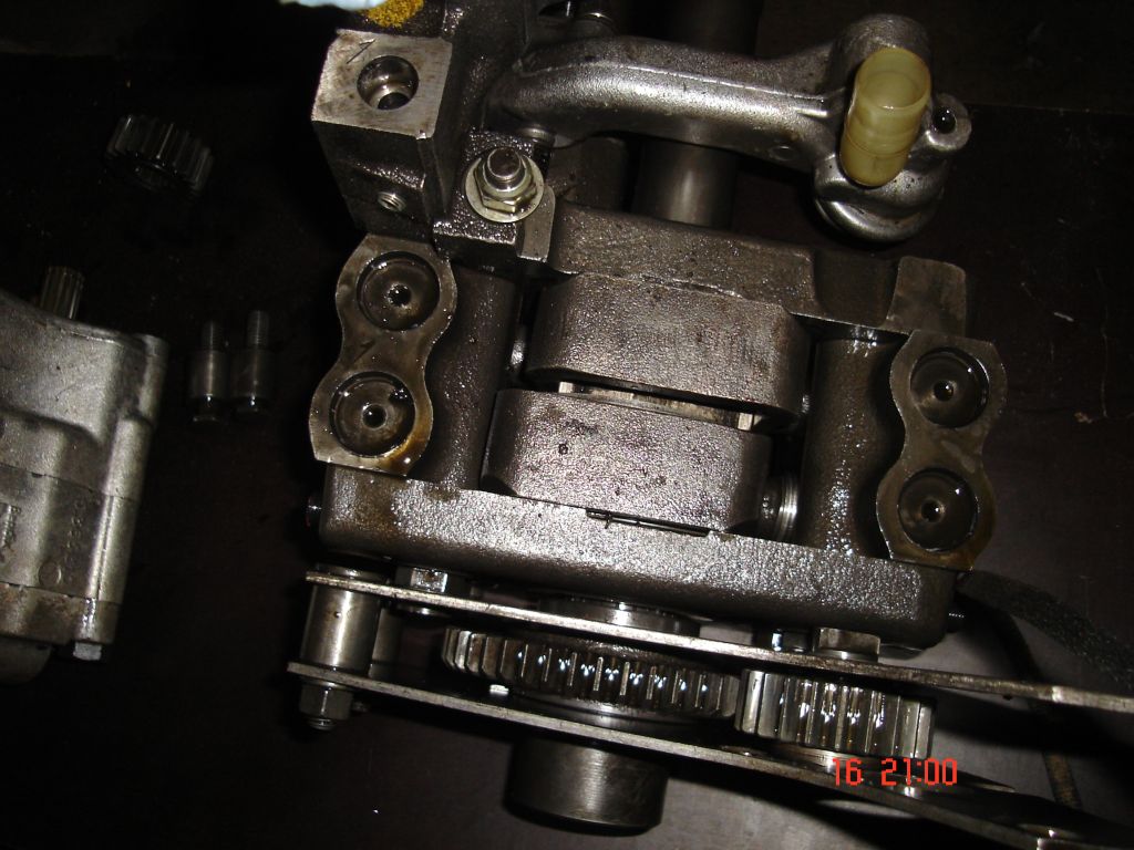
My 565 was without auxiliary pump, so instead of a gear wheel it had ordinary splined sleeve on lift pump drive shaft. The pumps themselves are the same. IMO there must be several kinds of these auxiliary pump's drive gears. For example this shaft rotates 1000 rpm because of lowering gear on PTO. On the other hand MF tractors with ground speed PTO have only 540 rpm rotation on this pump. So the gear ratios or the auxiliary pumps are different, because the given output is the same. Some tractors are with plain MP pump, probably with own kind of gear set. Or maybe not, I don't know? The number of splines on shaft is the other thing I'm unsure of. This has 21 splines as 1000 rpm PTO stumps usually have.
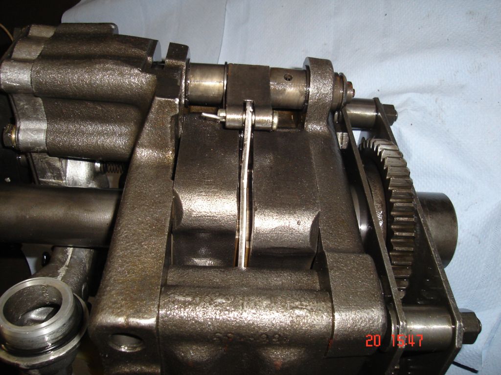
The ring and rod part between two boxer pistons affects some back and forth rotation to valve spool.
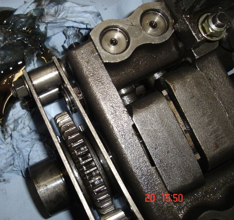
The plates are fastened with circlips to lift pumps special nuts. My 565 had similar nuts.
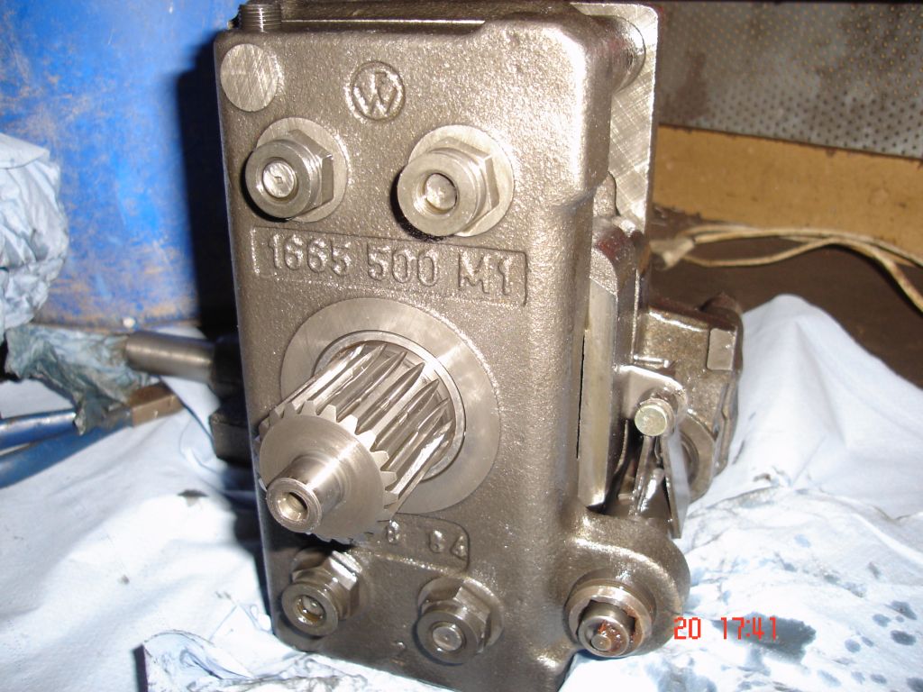
The lift pump was repaired with a similar procedure as I made this MF 565 pump repair.
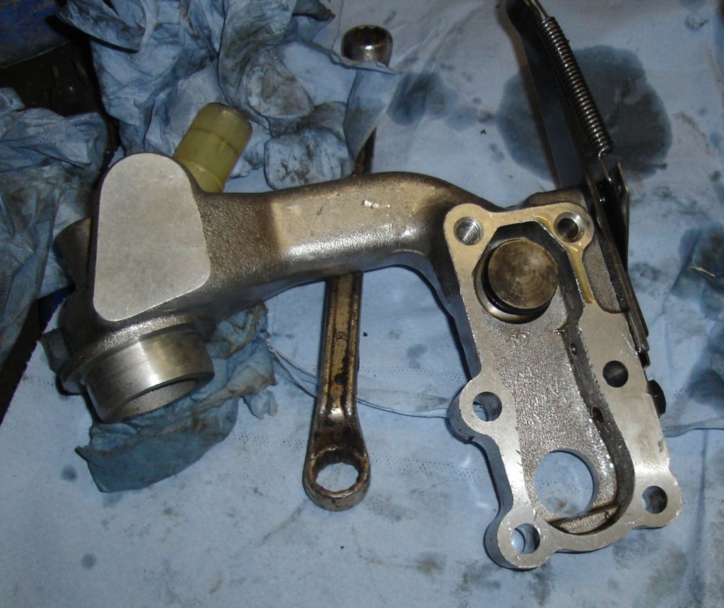
The intake manifold for the lift pump, auxiliary pump's suction is from this too. The one direction valve seen in picture is for adjusting linkage's lowering speed (draft control). When lowering the linkage, the control valve's spool is moving towards this chamber, because the other end of the spool is draining out oil from the lift cylinder. The oil between spool and one direction valve don't let the spool move until some oil gets out through small hole on the right. So altering the hole size, the lowering speed is controlled too.